| Working on the Gemini Program - Almost 60 Years Ago by: Hugo Kann |
|
|
I was a member of the original design team. My specific task was designing the receiver for the HF radio. Some of the engineers on the design team whose names I can recall were, Kent Black [1] (yep, that Kent Black), Howard Jackson [2], Ernie Moes [3], and an engineer named Sullivan (no, not George W. Sullivan). Eventually, after the design phase had been completed, I became project engineer during the qualification testing and manufacturing phases. I should note that because of time constraints, the qualification testing and the manufacture phases were run concurrently. Building the radios before qualification testing had been completed, i.e., their design not having been thoroughly vetted almost got us into some really serious trouble. Unique and Challenging Design Requirements1) To withstand the rigors of a rocket-propelled launch, the radios had to meet stringent shock, vibration, and acoustic noise specifications. The solution was to fill each module with a compound that after curing turned into rigid foam. The tricky part of that operation was that the compound expanded while curing. Jim Blin and his crew figured out the exact amount to be injected so when cured, the rigid foam would completely fill a module yet not overflow its sides. Encapsulating all electrical components within rigid foam presented a problem, though, if during final tests a component had to be replaced. This was a difficult and time consuming chore; specially trained operators, using dental tools, had to carefully dig down and around a faulty component, creating a large enough cavity in the foam for the replacement work to be done. Digging out and replacing one of the vacuum tubes was an especially delicate process. Yes, the final RF stages of both the UHF and HF transmitters used vacuum tubes, even though the RF power output of the transmitters was only 3 and 5 Watts respectively, reliable transistors for that application were not yet available. 2) The radios had to be hermetically sealed because they were located on the outside of the crew cabin. The seals had to remain intact after the stresses of a prolonged exposure to the vacuum of space and a reentry into the earth’s atmosphere. Finally, after splash down, the hermetically sealed radios were submerged under several feet of sea water. Remaining in a working condition after splash down was especially important for the HF radio— its signal was used for locating the floating capsule. And Then the Ship Hit the SandCase Failure Unlike the Apollo Command modules which floated upright after splash down, the Gemini capsules floated on their sides with the two hatches facing up and the radios, being located on the opposite side, being immersed under up to four feet of sea water. To prevent corrosion during the immersion, the outside of the cases were covered with a 50 millionth-thick layer of gold plating. The original design called for the cases to be sealed using soldered tear strips, the same method used for hermetically sealing aircraft instruments. As part of qualification testing, one of the sealed radios was placed in an altitude chamber and subjected to a vacuum for 48 hours. After removal from the altitude chamber, the radio’s case looked deformed, it had ballooned. However, considering what happened next, the deformed case was of little concern. After completing the vacuum test, the radio was immediately immersed in a barrel filled with four feet of synthetic sea water. After completing the immersion test, the case was found to be full of water - the solder seals had failed! Although solder seals provide very little mechanical strength, they had been used by Collins Radio Company for hermetically sealing aircraft cockpit instruments for decades without any problems. However, there is no comparison between the stresses on hermetically sealed instruments in aircraft cockpits and the Gemini radios being exposed to the vacuum of space for a prolonged time. It became apparent that hermetic seals without robust mechanical support would not work for equipment mounted on the exterior of a capsule. The next morning after the immersion failure, a Sunday morning, we had a meeting with the director of engineering, John McElroy [4], in his office trying to figure out what needed to done. Warren Fackler, the mechanical engineer on the program, was tasked to come up with a solution. Warren immediately went to work and came up with a complete, from scratch, redesign of the cases for both the UHF and HF radios. For a sealant he chose a Dow Corning product called “Silastic” (a portmanteau of ‘silicone’ and ‘plastic’). It’s the same stuff you can now buy at Menards for caulking around your bathtub. The caulk gives off a distinct vinegary smell as it cures. But Warren’s design also incorporated mechanical features that precluded any stresses being exerted on the sealant itself. For part of the manufacturing process of the redesigned case Warren chose a then state-of-the-art process called “electron-beam welding.” He had found a company in Chicago that looked like it could weld the seams of the cases and he and I visited the company. One of the impressions from that trip that still sticks in my mind after almost 60 years is that the welding equipment was mounted on top of a granite column that went down to bedrock. We were told that that was done to keep the electron beam from moving due to extraneous vibrations. I am still impressed with what Warren accomplished under the tremendous pressure of the time constraints. But here was one more problem, albeit, by comparison, a minor one. The Silastic sealant would cure too slow in the plant’s low humidity, about 12% at that time. The solution was to move the sealing process — including a workbench, the supplies and tools needed, and the assembly operator, into a climate chamber with the humidity level cranked up to a level sufficient for faster curing of the sealant. Of course the high humidity did not do much for the female assembly operator’s hairdo. |
| HF Radio Power Supply Failures | |
|
The input voltage of the radios was specified over a range of 18.0 to 32.6 Volts. Linear voltage regulators were too inefficient to meet such a wide range of input voltages and switching-mode power supplies were chosen instead. The use of solid-state switching-mode power supplies was still relatively new at that time. In the mid-1960s, the Gemini radios may have been the first Collins products that used such a power supply. It wasn’t until the HF radios were in full production and also going through their final acceptance testing that the power supplies started failing — some of the 1N647 bridge rectifier diodes for the 290 Volt B+ line would fail and in turn take out the switching transistors. At the suggestion of the diode manufacturer we replaced the 1N647s with 1N649s for their higher Reverse Voltage (VR) of 600V versus 400V respectively. But the power supplies were still failing! Looking at the voltage and current wave forms of the square wave on a dual-trace oscilloscope showed no obvious problems (Figure 1). The problem became obvious, though, when displaying the current through the diode on the vertical scale and using the voltage across the diode for creating the horizontal sweep (Figure 2). What that did in effect was to compress the flat part of the waveform’s ON and OFF states to the dots on the left and right respectively and show the transition between states greatly expanded. The problem was obvious. The diode turned off too slow after the polarity reversal, at its peak, with a voltage of 300 volts applied across the diode, a current of 150mA flowed through the diode in the reverse direction. Replacing the 1N64X diodes with SF10 diodes from Semtech solved the problem. The SF10 diodes had a Reverse Recovery Time (TRR) of 35ns. That parameter wasn’t even specified for the 1N64X diodes. In hindsight, after the reason for the diode failures had been determined, it was pretty clear why the 1N647 or the 1N649 diodes were too slow for that application. Now someone may say: “Duh! It obviously takes a faster diode for rectifying a five KHz square wave than one used for rectifying a 60 cycle sine wave.” In retrospect though, my thoughts are that back in the 1960’s there was no prior experience with using solid-state switching-mode power supplies in high voltage applications. It is still a mystery to me, however, why the diode problem did not rear its ugly head during breadboard and engineering model testing of the power supply. |
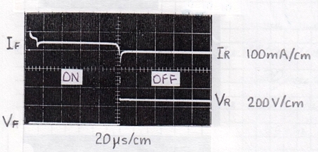 Figure 1 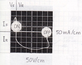 Figure 2 |
|
Zener Diode Problem
For transient-spike protection, the original design called for a 35V Zener diode to be placed directly across the DC input line. Without a series resistor to limit the current, when one of the diodes failed it put a dead short across the DC input line. Fortunately, this happened before any radios had been shipped. As a result of the failure, the Zener diodes were eliminated. |
|
| UHF Tube Problem | |
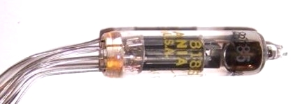 Figure 3 Type 8185 sub-miniature triode. |
The UHF transmitters used a pair of type 8185 (Figure 3) sub-miniature triodes operating in parallel in the final RF stages. Sometimes, after a transmitter had been turned on for the first time, the RF power output would slowly droop. It did not happen often, but to weed out any tubes with that characteristics, we went to a 24-hour burn-in of all UHF transmitters while continuously recording the power output. After the burn-in we could look at the data and see whether any tubes needed replacing. When there was decrease in power output, both tubes had to be replaced because we had no way of telling which one of the tubes caused the problem. Before the first launch, based on a reliability study, the second UHF radio was declared as not necessary as a back-up unit and was eliminated. Considering the problem with some of the tubes and that the capsules were configured for two UHF radios, I did not feel comfortable with that decision. But it wasn’t my call. |
|
Conductive Epoxy
The exterior foam surfaces of the HF radios’ power supply modules were covered with an conductive epoxy. This was intended to keep noise generated by the switching-mode circuitry, running at about five kHz, from interfering with HF receptions. However, the conductive epoxy did not provide sufficient shielding and was replaced by metal shields that were tack soldered to the metal edges of the power supply modules. Some AnecdotesThe HF and UHF Frequencies Were Classified Information During the design phase of the program I spent much of my time in a screen room working on the HF receiver module. I had strict instructions to change the setting of the signal generators to a frequency other than the Gemini one whenever I left the screen room. That was done to prevent someone from seeing which frequency the astronauts would be using. I followed the rules to the letter, but it wasn’t really necessary. One of the amateur radio magazines had already published the frequencies of both the UHF and HF radios. “Don’t Put Tape on ‘My’ Walls!”We had set up a command post in a conference room for monitoring the progress, down to the individual module level, of each HF radio through the assembly and testing processes. The people usually in the room were engineers, production coordinators, and expediters. Also with us most of the time, looking over our shoulders, was Bill Mayfield from McDonnell. For keeping track of it all, we made up a chart that had milestone bubbles with expected completion dates for each manufacturing step. We could see the status of several radio from start to finish. The chart we had taped to one of the room’s walls, where it stretched across its whole width and half its height. One day a guy from maintenance showed up and started chewing us out for having put tape on ‘his’ walls. Those of us in the room at the time were pretty well stressed out trying to keep things moving through two consecutive eight-hour shifts in the factory. (Because of the case and the diode problems mentioned above, Collins was dangerously close of not meeting its delivery schedule.) The maintenance guy didn’t stick around long, though. We had other priorities than worrying about peeling off a little paint when the tape was removed. He left the room rather quickly when he realized that he was in imminent danger of getting bodily tossed out. After that episode, we heard no more about tape on the wall. The work ethics of the 1960’s was different from today’s. During that crisis we spent most of our waking hours at the plant, including many weekends. That’s how it was. Without giving it a second thought, we worked until the job was done. Acoustic Noise TestOne part of the qualification test program called for the radios to be exposed to a specified level of acoustic noise. The only lab we found that was able to generate that level of acoustic noise was at a General Electric facility in Burlington, Vermont. John Zinkus and another engineer headed for Vermont in a company station wagon loaded down with all the test equipment and power supplies needed to take performance data before and after the acoustic noise test, the test equipment pretty much filled the back of the vehicle from behind the front seats to the back door. During the long drive to Vermont, John developed a severe case of Hemorrhoids and needed to come home. I flew to Burlington to take his place. It was in the autumn of 1964. Flying relatively low over the state in a propeller driven plane, the view of the maple trees in their best fall colors was awesome. The acoustic noise test was conducted inside of an anechoic chamber. Working inside that chamber with a zillion cones sticking out from its dark-grey walls and with our voices sounding muffled was really spooky. After the radios had passed the test we loaded up and headed back to Iowa. |
|
Gold Plating
The first attempt at gold plating the aluminum cases didn’t turn out too well. But the gold plating wasn’t the problem. It was the copper flash between the gold plating and the aluminum case that had peeled off (Figure 4). The problem was soon solved and there were no further problems with the plating. Argon Back-FillIt was more or less industry practice for hermetically-sealed equipment such as aircraft instruments, relays, etc., to be first evacuated and then back-filled with nitrogen. Back-filling using nitrogen was also planned for the Gemini radios. But one day we received instructions from McDonnell that the back-fill gas had to be changed to argon. The reason given for the change was that the small molecules of nitrogen molecules might migrate through the glass envelopes of the vacuum tubes and contaminate their innards, the larger molecules of argon would be less likely to migrate through glass. Although it looked like overkill, changing from nitrogen to argon wasn’t a big deal. University of Iowa’s Injun IV ProgramOver the years, the University of Iowa, under the leadership of Dr. James Van Allen, developed satellites in the Injun series to study radiation and magnetic phenomena in the ionosphere and beyond. The Injun IV satellite was the last in that series and for that one they needed an HF receiver. The rugged design of the Gemini HF receiver was a perfect fit. All we needed to do was change the receiver’s frequency to the one used by the U of I program. The Gemini HF receiver’s frequency was determined by a crystal filter at the front end. We changed the filter to one tuned to the Injun IV frequency and also changed the crystal that controlled the frequency of the local oscillator. Sometime in the late 1960s I delivered two of the modified receivers to the U of I Physics Lab in Iowa City. |
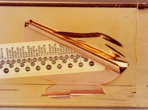 Figure 4 The Copper separated from the Aluminum casting, taking the Gold with it. |
|
Leak-Proofed Voice Control Center
I know little about the Voice Control Center because I was not involved with its design or its manufacture. I do remember one of its features, though. It was sealed to make it leak-proof, even though it was located inside the crew cabin. That was done for protection in case a urine bag would rupture, as had happened during one of the Mercury missions. |
|
|
The Team Photo
Shown in the photo, dated February 12, 1965, are the three members of the original design team that were still assigned the Gemini project then. The rest had been reassigned by that time to other projects. Mechanical engineer Warren Fackler is on the right, Vic Holec [5], project engineer on the Voice Control Center is in the middle and on the left is yours truly, project engineer for the UHF and HF radios. Shown on the bench from left to right are the Voice Control Center, HF Transceiver, and UHF Transceiver. The Final GlitchBecause the launch date of the first Gemini mission was getting very close, in March of 1965, I was hand-carrying an HF transceiver directly to the Kennedy Spaceflight Center, instead of it being delivered to McDonnell in St. Louis. The first leg of my trip to Florida was a flight to Chicago that made an unscheduled stop in Moline, Illinois. The pilot announced that this was as far as the plane would go and that the passengers had to deplane. All the passengers were in the Moline terminal waiting for an announcement. But an announcement never came because at the time of our unscheduled arrival no gate agents were on duty. I was getting worried about missing my connecting flight in Chicago and decided to go over to the fixed-base operator to see whether I could get a charter flight to Chicago. I thought that having a letter signed by Art Wulfsberg (see Figure 6, below) might help, but no charter flights were available on such short notice. I went back to the terminal and almost missed getting on a replacement plane that had been brought in. I still shudder to think about the repercussions had I missed that flight while still over at the fixed-base operator. |
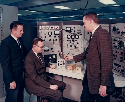 Figure 5 Hugo Kann, Vic Holec & Warren Fackler - February 12, 1965 |
|
After my Florida flight landed in Orlando, I had to drive to the Cape in the dead of night on a two-lane highway. I could only see what was straight ahead, but from the smell I could tell that that I was driving through middle of a swamp. I even had to stop once for an alligator who was leisurely crossing the road in front of me. No deer-in-headlight look for that big fellow. Yep, I wasn’t in Iowa anymore. I did manage to arrive at the Cape and hand over the radio at the Space Flight Center in time. The trip had its rewards, too. I got a tour of the whole facility and they even took me up the gantry and let me have a look into the inside of the capsule where technicians were in the final phases of installing equipment. I noticed a lot of loose hardware, nuts bolts, etc., on the floor of the cabin. I am sure that all got cleaned up. Without a clean-up, all that stuff would have been a real hazard while floating around inside the cabin during weightlessness in space. |
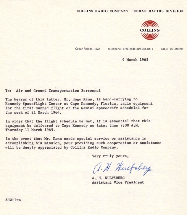 Figure 6 |
|
Listening to the Astronauts’ Transmissions
As the date for first Gemini mission approached, I contacted one of the major TV antenna manufacturers about modifying one of their UHF TV antennas for reception at 297 MHz. After I explained Collins’ role in the Gemini program to whomever I was talking to, he said they could - and after a week or so, we received a modified antenna, free of charge. We mounted the antenna, pointing south, on the roof of what was then called the MBA1 Building. We were able to briefly listen to the astronauts’ transmissions whenever their capsule rose above the southern horizon. I taped some of the transmissions and later played them for some of the Collins brass. TV InterviewSometime after the Gemini missions had started, I was asked to do an on-camera interview at KCRG TV. I was to talk about Collins’ role in the program. The interview went well except near the end the reporter slipped in a loaded question, as is their ilk’s wont. I don’t remember the details, something related EVAs (Extra Vehicular Activities), but I managed to successfully parry his question. Final CommentUnlike the Apollo equipment, the Gemini radio were located outside of the crew cabin and could not be serviced or swapped out during a mission. Had there been a failure of one of those radios during a mission, it would have seriously stained Collins’ unblemished reputation for building top quality equipment annd might have adversely affected the Apollo contract. |
 |
| —Originally published in November 2019 as 'Remembering Working on the Gemini Program Almost 60 Years Ago' |
|
[1] Kent Black retired from Rockwell International in 1996 after serving as Chairman of the Board, Executive Vice President and CEO. He is presently living with his wife, Karen, in Texoma, Texas. |