| RADIO AGE for May, 1926 | The Magazine of the Hour 33 |
Full Details of a
Short Wave Transmitter
BY ARTHUR A. COLLINS |
| (Radio 9CXX) |
|
A PERSON who desires to gain a more intimate knowledge of high frequencies, and one who is willing to devote a good deal of time and study to his work, would be interested in the construction of a high frequency transmitter.
A previous article has discussed the construction of a high frequency receiver for gaining an acquaintance with the amateur activities on the shorter wavelengths.
In this article I shall attempt to give some helpful Information for a person just entering the transmitting end of the amateur game.
A grievous mistake often made by initiates is the thought that by copying exactly the equipment of some person who has been successful in any one line, they will be able to duplicate his results.
This is rarely the case.
The actual equipment counts for very little in the final analysis; it is the operator’s knowledge of the technical why’s and wherefore’s that brings outstanding results.
With this thought in mind, I am offering the following information for what it may be worth in starting the layman on an individual path which may lead to achievements of his own.
Circuits
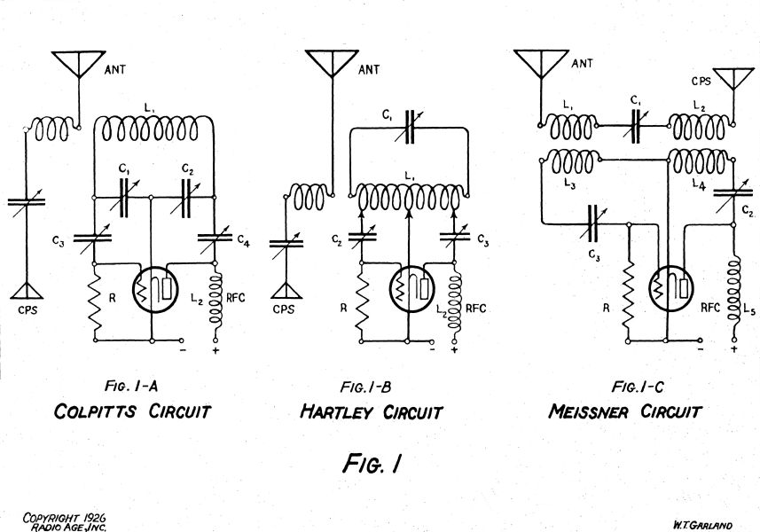
THERE are fundamentally three oscillatory vacuum tube circuits, known as the Hartley, the Colpitts, and the Meissner, each with its own advantages, but of the three, the Hartley is perhaps the most popular among amateurs for high frequency work.
|
The theoretical operation of each of these three circuits will not be entered into here.
Figure 1 shows these three elementary circuits.
The Colpitts and Hartley circuits both have a “tank,” or frequency determining circuit included in the primary, or vacuum tube circuit, the only difference between these two lying in the means of grid excitation, which is accomplished in the former by capacitative, and in the latter by inductive, reactance.
The Meissner circuit differs from the Hartley circuit only in that the secondary, or antenna, circuit comprises the tank circuit, and for this reason this circuit is the least desirable of the three, since any change in the antenna constants will result in a change of frequency, which is very objectionable on the short wavelengths.
The Colpitts circuit possesses the decided advantage that the ratio of external capacity is high with respect to the internal capacities of the tube.
This relation keeps the radio frequency current values within the tube elements at a small value, thus reducing hysteresis losses in the tube insulation, and also the ensuing possibility of damage to the tube when operating on high frequencies.
When a transmitting circuit is being chosen one thing must be kept in mind: although very good results can be obtained with any circuit, a thorough knowledge of the operating characteristics of all of them is almost a prerequisite for success.
It is worth while to try them all with this end in view.
|
Construction Data
FROM a practical standpoint, the primary consideration of the beginner is usually the power tube.
High power is by no means essential for long distance work on the short wavelengths.
Single UX210’s and even amplifier tubes daily connect U.S. amateurs with fellow “hams” in Australasia, Europe, and South America.
High power is necessary only to maintain absolutely reliable contacts under adverse conditions, and inversely, to lessen one’s dependence on kindly fates.
I would not advise a novice to commit his initial crime on anything larger than a UX210 Radiotron.
Parallel operation of tubes, at least in excess of two tubes, is highly impractical on high frequencies.
The “A” type thoriated filament Radiotrons are favored above all others for high frequency oscillators.
These can be bought in different sizes with rated outputs from 7.5 to 1000 watts, according to the size of your pocketbook.
A second problem is obtaining a source of power for the transmitter.
The ideal supply is pure D.C. to plate and filament, but this can usually be only approximated in practice because of financial considerations.
An amplifier tube may be supplied by dry cell “A” and “B” batteries, storage cells can be used with larger tubes, but their cost and upkeep soon become prohibitive for most of us as the power is increased.
|
| 34 RADIO AGE for May, 1926 | The Magazine of the Hour |
|
When an appreciable amount of power is used, it is usually more practical to convert the A.C. from your power mains.
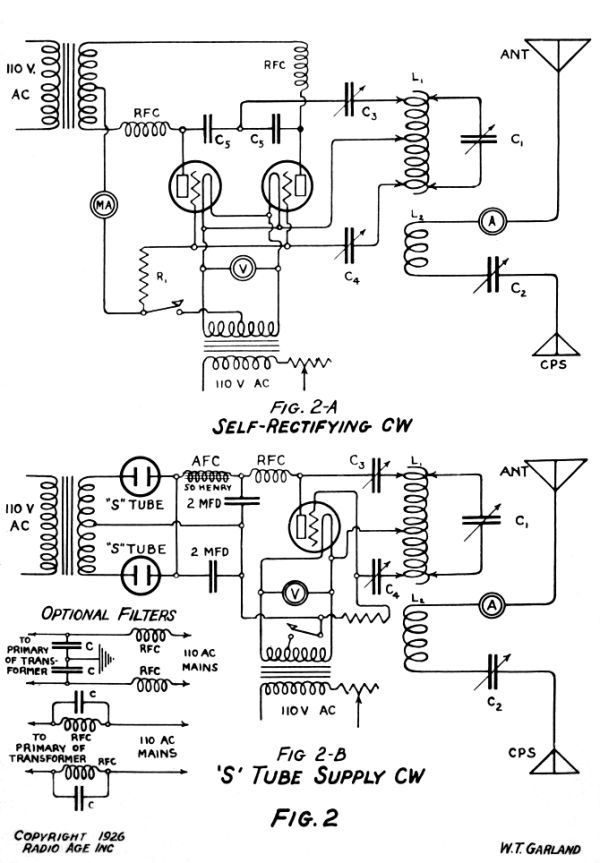
Common ways of doing this are by using a motor-generator set, kenotrons (thermion rectifiers), “S” tubes (gaseous rectifiers), chemical rectifiers, synchronous mechanical rectifiers, or by self rectification with two power tubes (one on each side of the A. C. cycle).
These systems are named in order of their excellence, and also in order of their costliness–take your choice and pay the piper.
Although good results can be obtained with a chemical rectifier, it is perhaps the least economical of any system, since one will require constant attention, and if the operator values convenience, it would be better to invest in a more reliable source of plate supply.
Filter Circuits
SMOOTHING or filter circuits should be used with any of the above power systems. A suitable smoothing system consists of two 2 mfd. high voltage condensers across the supply line separated in the positive lead by a 50 Henry audio frequency choke coil.
Power tube filaments are best heated by A.C. from a small step-down transformer with the grid and plate returns brought to a center tap in the secondary winding.
It is best to buy specially designed transformers from a reputable company.
In regard to power supply, two things cannot be over-emphasized.
Do not exceed the rated plate and values of your tubes, and know exactly what you are putting into the tubes.
Invest in reliable instruments for measuring filament voltage, plate and grid current, and even plate voltage, if possible.
Observation of these suggestions will result in longer tube life, increased efficiency, improved wave character, and a greater chance for the operator to become acquainted with correct methods of engineering.
The radio frequency circuits next demand attention.
|
“Low-loss” condensers adaptable for transmitting are being placed on the market by reputable firms.
The condensers in the tank (d) and antenna circuits (c2) in Fig. 2 and 2-A should be of about 100 mmfd. capacity and must be double or triple spaced for powers of 50 watts and above.
Well designed variable receiving condensers of 150-250 mmfd. capacity will serve in the grid circuit (c1) and also in the plate circuit (c3) for low powers, but, since the plate condenser must withstand the entire plate voltage, it is necessary to use specially designed mica condensers in the plate circuit for the higher powers.
Such condensers are sold by the Radio Corporation of America and by the Dubilier Company, and should have a rated breakdown voltage considerably in excess of the plate voltage.
Westinghouse mine locomotive condensers may be also used.
They may be secured through your local power company.
Very acceptable inductances can be made by carefully winding quarter or three-eighths inch copper tubing around a piece of table leg, bed-post, or the like, about four inches in diameter, cutting off the required number of turns, and then carefully spacing the turns by sliding a flat object between them.
Coils made in this manner can be supported on slender glass tubes, and should be rigid enough for practical purposes without further dielectric being introduced into their field. L1 and L2 should be approximately 10 and 5 turns respectively for 7500 kilocycles (40 meters) and 5 and 3 turns respectively for 15000 kilocycles (20 meters).
R.F. Chokes
IMPORTANT items not to be neglected are the radio frequency chokes in the power leads to the plate and grid.
For 20-40 meter work, coils consisting of 75 turns of No. 22 D.C.C. on a 1-inch hard rubber forms are quite acceptable.
|
These coils should be placed so that magnetic coupling to the inductances is at a minimum.
Efficient radio frequency choking in the power leads will prevent loss of power and reduce blanket interference in the immediate vicinity of the transmitter—an important consideration if you want the family to hear its bed-time story.
The choke in series with the grid leak, although not shown in the diagram, is fully as important as the plate choke and should be inserted between the grid terminal on the tube socket and the grid leak.
The instruments can be set up very neatly on a breadboard or drafting board, or even on a table-top, arranged much as they are represented in the circuit diagrams.
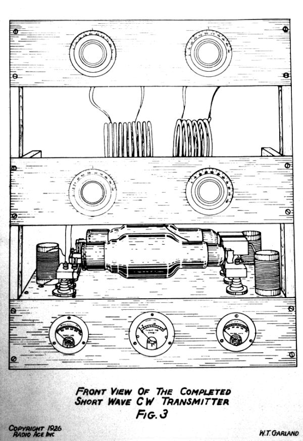
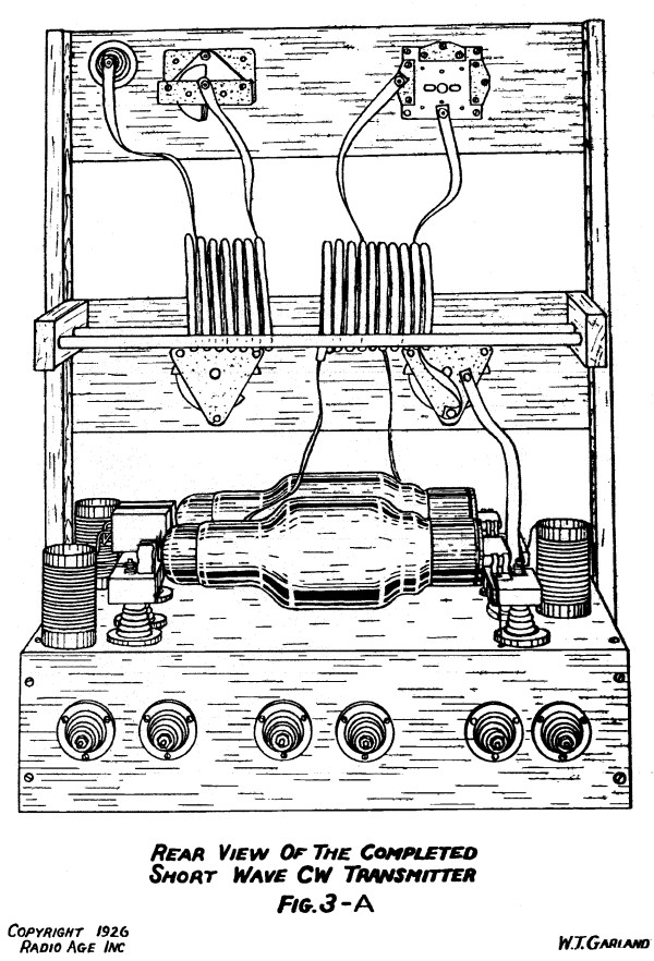
A more permanent arrangement can be constructed in the manner shown in the diagrams of the “500 watt,” 37.5 meter transmitter used at 9CXX.
It is usually quite preferable to have the transformers and rectifiers separate from the transmitter itself.
All radio frequency leads should be of heavy copper, as short and direct as possible, and supported in air as much as possible.
Tube sockets should be of the best quality porcelain or glass.
Following out the idea of low-loss design, all leakage paths in the radio frequency circuits should be reduced to a minimum and should be long and narrow in a good dielectric.
Hard rubber, Pyrex glass, glazed porcelain, and white-pine boiled in paraffin are considered the best insulators at high frequencies.
Whether mounted on a panel or on a “breadboard,” all apparatus should be arranged so that stray magnetic and electro-static fields around the instruments will interfere with each other as little as possible.
Operate Near Fundamental
THE antenna system will offer difficulties of its own.
Large antennae have been operated successfully at harmonics on 40 and
|
| RADIO AGE for May, 1926 | The Magazine of the Hour 35 |
|
20 meters, but smaller antennae operated close to their fundamentals are now gaining favor among amateurs.
A single conductor vertical antenna with a single conductor horizontal counterpoise is a common form of this latter type.
If one chooses to erect a system of this type, the following dimensions will be approximately correct: 40 meters, antenna and counter-pose both 30 feet in length, and for 20 meters, both antenna and counterpoise 15 feet in length.
A third type of antenna fast finding favor because of its polarizing properties is known as the Hertz antenna, and consists of a single horizontal conductor one-half of one wavelength long coupled to the oscillator by a R.F. feeder attached near the center. (This general scheme for reception was shown on page 14 of the April issue of RADIO AGE.)
The amateur will do well to adapt his antenna system to his location. (City cliff-dwellers please take notice.)
An open location free from obstructions is highly desirable, but unusual results can be obtained in a very poor location if care is taken to make the best use of the available space.
Keep the system as free from surrounding buildings, trees, wires, etc., as physically possible.
Since short wave antennae are usually diminutive, it is a good plan to locate the transmitter on an upper floor, if it cannot be housed separately, so that the lead-ins from antenna and counterpoise will not detract from the effective height of the system.
It is a clever scheme to bring the leads into the house through the center of a window-pane, thus reducing the heavy losses encountered in most lead-in bushings.
No. 8 or 10 enameled magnet wire will not corrode and is sufficiently heavy for a medium powered transmitter.
The insulators should be long and slender of glass or porcelain-glass towel bars will usually serve admirably.
Needless to say, all joints must be well soldered.
Every antenna system has a frequency on which it operates most efficiently, so for best results this frequency, determined by experiment, should coincide with the operating frequency of the transmitter.
|
Operation
OPERATING a transmitter at highest efficiency requires, first, a thorough knowledge of “what makes the wheels go around,” and, second, plenty of experience with blown tubes, blasted hopes, and depleted finances.
Leaving the second requirement to the fates, I will briefly describe the method of putting a simple Hartley circuit into operation.
Check over the wiring, arrange the clips on the primary inductance in somewhat the relative positions shown in the circuit diagrams, apply the rated voltage to the filament and about 25% of the rated voltage to the plate.
If there is no display of fireworks, touch the ends of the primary inductance with a wooden-handled screw-driver.
A lively arc to the screw-driver indicates that the circuit is oscillating.
With an accurate wavemeter (an absolute requisite for every transmitting station) find out on what wavelength the set is oscillating.
By varying the tank circuit inductance and capacity, the set can be made to oscillate on the desired wavelength.
The grid and plate circuits are now tuned for greatest efficiency, which is usually indicated by lowest input to the plate.
Now place the antenna circuit in resonance with the driver and apply full power to the plate.
The increased input and newly added load on the oscillator will require careful readjustment of all the circuits for greatest output.
Re-check the wavelength and listen for harmonics in your receiver to discover whether or not the emitted wave is steady in character and free from thumps and warbles when the key is operated.
With a little additional nursing, the set should be ready for business-but don’t expect to talk to Timbuktu first thing.
Really satisfactory operation can be expected only after a good deal of midnight oil and honest toil have been expended in “rehashing” the apparatus.
The character of the emitted signal counts for fully as much as signal strength in long distance work under adverse conditions.
A swinging antenna will cause a wobbly note, and a poorly filtered power supply will cause a deep growl instead of a flute-like D.C. note.
|
In each case the remedy is almost obvious. Loose coupling to the antenna, now required in all station licenses, has been of great assistance in sharpening and steadying our signals.
Crystal Control
A TRANSMISSION system not previously mentioned consists of a master oscillator-power amplifier arrangement.
The only type of this system that is outstandingly successful on high frequencies utilizes a quartz crystal oscillator, frequency doublers and power amplifiers to supply an absolutely unvarying frequency to the antenna—the ideal arrangement, but too complex and expensive for the unseasoned experimenter.
Even if not pursued seriously, the amateur game is an avocation decidedly worth-while.
A high frequency transmitter can gain you lasting friendships with young fellows all over the world.
It can be a novel, yet effective, means of studying that ever-interesting abstraction, human nature, or it can be a substantial foundation upon which to base later scientific work.
It has been impossible in these pages to more than outline a few of the more essential points which must be considered in the construction of an amateur high frequency transmitter.
Supplementary reading should, of course, be undertaken before one goes into the subject seriously. Ballantine’s RADIO TELEPHONY FOR AMATEURS is revered almost as gospel by the amateur fraternity.
Interested parties should by all means join the American Radio Relay League (Headquarters, Hartford, Connecticut), a mutual organization of practically all the active amateurs in the world.
A membership will be a means of placing you in touch with all the worth-while developments in the amateur game.
The real thrill in amateur work comes not from talking to stations in distant lands, not from receiving multitudes of “QSL” cards from all the world, although these are things to stir your imagination, but from knowing that by careful and painstaking work and by diligent and systematic study you have been able to accomplish some feat or establish some fact that is a new step toward more perfect communication.
|
 |
| |
 |
| |
 |
| |
 |
| |
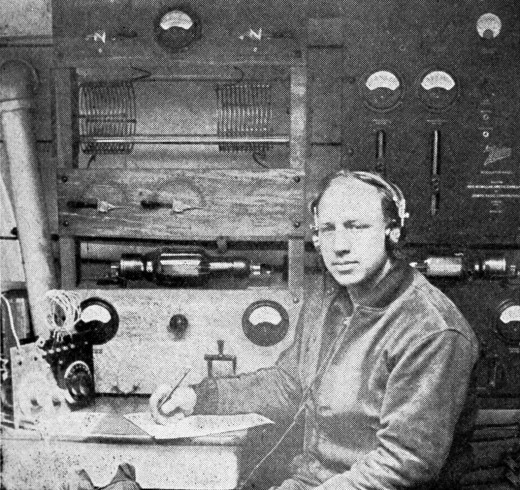
I added this image of John Reinartz, 1QP, seated in front several of his rigs.
Note that the transmitter behind him is similar, in construction, to Arthur’s rack-mounted layout. In addition, we can see that John’s receiver uses the same squirrely coils as described in Arthur’s previous article about his receiver design.
Arthur and John had many learning QSOs - leading up to MacMillian’s expedition to Greenland and the Artic.
—Web Editor |
 |
|