| Reprinted courtesy ARRL. |
Grid-Bias Modulation of the 100-Watt Type
Power Amplifier
Operating Characteristics and Comparison with Other Systems |
| By Walter H. Wirkler and Arthur A. Collins, W9CXX* |
MODERN control-grid modulation is handicapped by some very questionable ancestry, one of the earliest attempts consisting of inserting a microphone in series with the grid leak of a triode oscillator.
This and other early arrangements were characterized by a low modulation percentage and a just as low order of intelligibility.
Fortunately, scientific treatment has eliminated such hereditary throwbacks and within the past few years high-quality grid modulation has been successfully applied to broadcast transmitters.1
However, these transmitters operated the grid-modulated amplifier entirely in the negative grid region so that the plate efficiency was limited to about 20% and the ratio of carrier output to tube rating was very low.
The type of control-grid modulation now under discussion involves the use of a.f, and r.f. drivers with good regulation so that the grid may be driven positive without distortion of the grid voltage.
* Collins Radio Company, Cedar Rapids, Iowa.
1 This type was described in the article, “Making Practical Use of Grid-Bias Modulation,” by R. A. Isberg, QST, Aug., 1932.—Editor.
|
The resulting higher output makes this arrangement comparable in performance to a Class-B linear amplifier using the same tubes.
While no particular novelty is claimed for the circuit or principles involved, data have been obtained which permit a rational method of design.
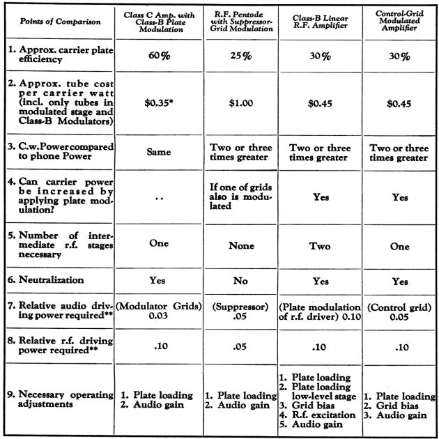
The table compares the advantages and disadvantages of control-grid modulation with three other leading systems of modulation, the comparison indicating this system as advantageous for certain types of transmitters.
The data in the table are based on the use of air-cooled tubes of the 211, 830-B and RK-20 types but are more or less applicable to larger and smaller tubes.
It will be seen that Class-B plate modulation still compares favorably with the other systems, retaining the advantages of low tube cost, low distortion and simple operating equipment.
The newer r.f. pentode amplifier with suppressor grid modulation is also easy to adjust and no neutralization or intermediate amplifiers are required.
These features recommend this tube especially for use in light-weight transmitters where a simple frequency shift system must be used and where these advantages off-set the somewhat higher tube cost.
|
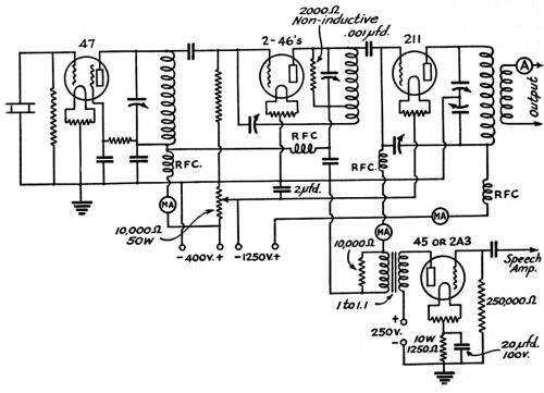
FIG. 1-SIMPLIFIED SCHEMATIC OF THE GRID-BIAS MODULATED TRANSMITTER
|
|
| QST - March, 1935 | 29 |
The r.f. power pentode is a relatively new development and the ultimate limitations of suppressor modulation cannot be definitely stated until further tube developments can be made.
The Class-B linear amplifier is practically ruled out for general purpose use because of the additional buffer stage required and because adjustment is so complicated that it can scarcely be made without the aid of an oscilloscope.
Control-grid modulation overcomes these disadvantages of the linear amplifier. The tube cost per carrier watt approaches the low figure for Class-B plate modulation and there is only one additional operating adjustment— that of grid bias.
A control-grid modulated transmitter is
|
particularly desirable where the full tube capacity may be used for c.w. telegraph operation so that the c.w. power is two or three times that of the 'phone power.
Likewise, Class-B plate modulators may be added without modifying the r.f. line-up when it is desired to increase the 'phone power of the transmitter.
Fig. 1 shows the simplified circuit of the grid-modulated transmitter.
It will be noted that the audio modulating voltage is applied to the grid of the final amplifier in series with the adjustable d.c. bias voltage.
he audio driving tube has a low plate impedance and it is coupled. to the transmitter by a transformer and resistor combination so that the audio voltage is not distorted by the flow of grid current.
|
| TABLE OF COMPARISON |
*In comparing initial cost, the cost of the modulation transformer should also be considered in Class-B plate modulation. **Figured as ratio of grid input to carrier output.
|
|
| 30 | QST - March, 1935 |
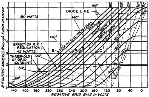
FIG. 2-CALCULATED GRID-BIAS MODULATION CHARACTERISTICS FOR A 211 TUBE
Showing the effect of r.f. grid excitation. Plate load resistance, RL; 2500 ohms; plate voltage Eb, 1250 volts.
|
|
Relatively high values of d.c. bias voltage are necessary.
Therefore, the low voltage power supply in the transmitter is arranged to furnish bias voltage to the last stage, adjustable by means of a potentiometer.
The grid current is quite low so that a small bleeder current is sufficient to maintain the bias voltage substantially constant at varying levels of modulation.
Good r.f. driver regulation is accomplished by using a low plate voltage intermediate amplifier with a loaded tank circuit directly coupled to the grid of the modulated stage, as with a Class-B linear amplifier.
|
Fig. 2 shows a series of modulation curves indicating how the r.f. output varies with the grid bias.
Any convenient value of r.f. excitation voltage may be used although slightly higher plate efficiency is obtained with higher values of r.f. grid voltage and correspondingly greater negative bias.
It is usually not desirable to have the operating angle exceed 180° at the most positive point on the a.f. cycle.2
The curves in Fig. 2 are calculated point-by-point by the method given by Everitt.3
Constant r.f. excitation voltage is presupposed.
|
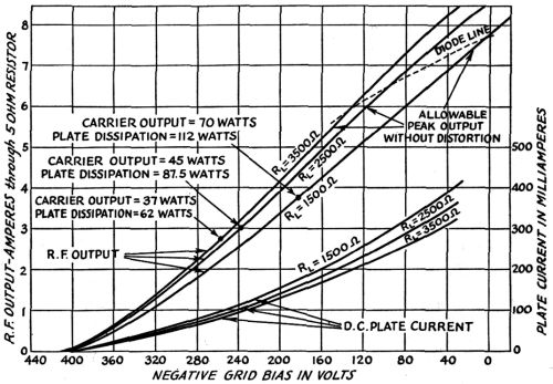
FIG. 3-CALCULATED GRID-BIAS MODULATION CHARACTERISTICS FOR A SINGLE 211 TUBE
Showing the effect of changing plate loading, RL Peak r.f. grid excitation, 310 volts; plate voltage, 1250 volts.
|
2 The “operating angle” indicates the portion of the r.f. cycle during which plate current flows, a full half-cycle being 180 degerees. See “Vacuum Tubes As Power Oscillators”, by D. C. Prince, Proc I.R.E., June, Aug., and Oct., 1923; also the paper referred to in the next footnote. —Editor.
3 W. L. Everitt, “Optimum Operation Conditions for Class-C Amplifiers”, Proc I.R.E., Feb., 1934.
|
|
| QST - March, 1935 | 31 |
If r.f. regulation is such that the r.f. voltage increases as the grid swings negative, the modulation characteristic will swing from one to another of the curves as indicated by the dotted line.
This r.f. regulation will therefore necessitate a greater a.f. swing for complete modulation and may introduce distortion because of non-linear grid impedance,
The r.f. regulation can be made negligible by proper artificial loading of the driver stage.
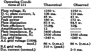
Typical operating conditions for a 211 operated as a grid modulated amplifier are given on page 62.
These conditions of operation are represented operating point, “A”, in Fig. 2.
As previously explained, any other operating point, such as “B” or “C”, may be chosen with only slightly different performance.
It is interesting to observe that if the excitation and bias were adjusted to correspond to the operating point “D”, and so that peak output occurs at “E” with an operating angle of 180°, the tube would function at peak output exactly as if it were a Class-B linear amplifier.
The plate load resistance should be as high as possible consistent with obtaining the required peak output before approaching the “diode point” or the point at which the instantaneous plate voltage approaches the most positive grid voltage.
The effect of using different load resistances with a given value of r.f. excitation is shown in Fig. 3. A load impedance of 2500 ohms is about the optimum value for a 211 operated under the conditions specified.
Lighter loading reduces the peak power output and heavier loading increases the plate loss.
The d.c. plate current is also shown on Fig. 3 and it will be noted that there is considerable upward curvature.
This curvature is evidenced in actual operation by the d.c. plate current “talking up” slightly under complete modulation.
The discussion of adjustment thus far has dealt with such intangible quantities as load impedance, operating angle, etc., and, it is now desirable to see how a specific transmitter may be tuned up without thinking about anything other than meter readings.
The transmitter is first adjusted for c.w. operation with the buffer plate coil unloaded and with the 211 operating as a Class-C amplifier.
The bias potentiometer is set at the proper point for Class-C operation (twice cut-off bias) and the
|
oscillator and buffer stages tuned for maximum excitation to the final amplifier.
The antenna is coupled to the final amplifier so that the plate current is 175 ma.
The transmitter can then be readjusted for 'phone operation as follows:
1. Increase antenna coupling until final amplifier plate current is 250 ma. Note the antenna current under this condition.
2. Remove the unloaded buffer tank coil and insert the buffer coil which is fitted with a shunt load resistor.
3. Increase the setting of the bias potentiometer until the antenna current is reduced to exactly one-half of the value obtained under “l”.
The transmitter is then ready for use.
With a constant pure tone signal, 100% modulation is indicated by a rise in the amplifier plate current of approximately 12 ma.
With speech, however, the rise is only about 6 ma.
Of course, the procedure given above is not necessarily applicable to every other set because the first adjustment for proper load impedance is affected by power supply regulation, etc., and is consistent for a single design only.4
Proper adjustment of another grid modulated transmitter of different construction really would require the use of an oscilloscope and an output measuring device for the initial determinations.
If some other design is to be used, it is well to choose an amplifier tube with adequate plate dissipation capability and a medium or low amplification factor.
4 George Grammer's article elsewhere in this issue describes methods for lower-powered transmitters.— Editor.
|
|
| 62 | QST - March, 1935 |
|