| Reprinted courtesy ARRL. |
A Universal Antenna Coupling System
for Modern Transmitters
All-Band Operation with any Antenna–Improved Efficiency–
Reduced Harmonic Output |
| By Arthur A. Collins, W9CXX* |
THERE is a very much more efficient and reliable way of transferring energy from the final tank circuit of a transmitter to the antenna than the customary arrangement using an antenna pick-up coil placed in an inductive relation to the plate coil in the transmitter.
Almost every user of high frequency transmitting equipment has had the exasperating experience of getting the transmitter itself tuned up properly and developing lots of energy in the final tuned circuit and then finding that the antenna refuses to draw the power from the transmitter.
This problem has become much more complicated in recent years because most high frequency transmitters are operated on several bands of frequencies, and it is usually desirable in amateur installations to use a single antenna on all bands.
Very few antennas with their associated feeder systems will resonate on all the desired frequencies without using some sort of complicated tuning arrangement at the transmitter end.
It is the purpose of this article to describe an impedance matching network which greatly simplifies this problem and assures that the energy from the transmitter is properly coupled into the radiating system, with the additional feature that all harmonics are very effectively suppressed.1
The system also makes possible the use of a single antenna and a single antenna coupling unit on all frequencies.
Fig. 1 shows the basic circuit involved.
It will be observed that two capacitors and an inductance are connected in a low-pass filter circuit resembling that used in plate supply systems.
The input side of the filter is connected across the output of the transmitter and the output side of the filter is connected to the radiating system.
By using variable condensers and inductors, it is possible to match the output impedance of the transmitter to any antenna input impedance which will be met with in practice.
This means that the transmitter can be coupled to any sort of an antenna whether it is a piece of wire 20 or 200 feet long.
* Collins Radio Co., Cedar Rapids, IA
1 Everett, “Output Networks for Power Amplifiers,” Proc. I.R.E. May 1931. —Editors.
|
First we shall consider the case of an antenna having a single lead-in wire (Marconi type or single-wire transmission line) and later show how the same system can be applied to an antenna with two lead-in or feeder wires.
These are rather broad claims for an antenna coupling circuit and the amateur will be immediately interested in how he can apply this system to his transmitter without wading through a lot of theory.
Therefore we shall explain the practical operation of the system first and let the theory ride until the last paragraph.
PRACTICAL ASPECTS
The two condensers C1 and C2 should have a fairly high maximum capacity, about 300 μμfd., and the variable inductance can be 30 turns, 2½ inches in diameter, 5½ inches long, tapped every five turns.
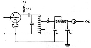
FIG. 1-THE BASIC IMPEDANCE-MATCHING CIRCUIT ARRANGED FOR COUPLING TO A SINGLE-WIRE FEED SYSTEM
See text for constants
For transmitters with powers up to twenty-five or thirty watts, condensers of the receiving or small transmitting size can be used.
Of course, both the condenser and the inductance must be of low-loss design.
Let us assume, first of all, that we want to couple a transmitter tuned to, say, 3600 kc. to a single-wire Marconi type antenna and the antenna is of any size which conveniently fits the back yard.
If the antenna happens to be an odd multiple of a quarter wave length long, it will have an input impedance of several thousand ohms.
In both cases, it will be purely resistive.
|
|
| QST - February, 1934 | 15 |
On the other hand, if the antenna is not a multiple of a quarter wave length long, its input impedance will be intermediate between these values and it will be reactive; that is, it will require the addition of an inductance or a capacity to obtain resonance.
The problem is effectively to match this antenna input impedance to the plate circuit of the final amplifier so that the tubes look into a pure resistance of exactly the right value for normal plate current.
Adjustment is accomplished as follows:
Disconnect the matching network from the transmitter at “A” and tune the transmitter plate current in the ordinary way so that minimum plate current is obtained in the final amplifier, indicating resonance. After the plate tank condenser is adjusted for resonance with the output circuit disconnected, it should not be touched again during the tuning procedure.
Next, adjust the tap on L1 to a point where resonance at the transmitter frequency is likely to be obtained.
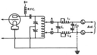
FIG. 2-THE BALANCED ARRANGEMENT FOR TWO-WIRE ANTENNA FEED
The approximate settings are 30 turns for 160 meters, 15 turns for 80, 8 turns for 40 and 5 turns for 20.
Set C2 at mid-scale, connect the output circuit to the transmitter at “A” and apply plate voltage to the final amplifier.
C1 should then be rotated rapidly until a dip is obtained in the power amplifier plate current.
Resonance in the output circuit occurs at this point.
The value of minimum plate current obtained may be higher or lower than that desired for satisfactory operation of the output stage.
If the plate current is not correct, rotate C2 slightly and then readjust C1 to restore resonance.
This procedure can be repeated using C2 to adjust the degree of coupling and C1 to restore the circuit to resonance until the correct plate current is drawn in the power amplifier.
An antenna ammeter placed in the antenna lead-in will indicate antenna current when C2 is adjusted to resonance.
The circuit is now properly adjusted and, after the signals are checked in the monitor, the arrangement is ready for use.
It sounds very simple, doesn’t it?
As a matter of fact, this system is much easier to adjust than many of the conventional arrangements using a coupling coil.
Volumes of equations have been written about filter networks, but in practice there is nothing so very complicated about their use even at radio frequencies.
|
One or two details of adjustment should be discussed, however.
It will be found that the adjustment of L1 is not critical.
As more inductance is cut into the circuit, the same results can be obtained up to a certain point beyond which the insertion of more inductance will make it impossible to obtain an impedance match.
Of course, C1 and C2 will have different settings when L1 is changed.
In general, L1 should be kept as large as possible consistent with obtaining proper impedance match.
This is the condition for lowest loss in the filter but these losses are negligible anyway if the apparatus is well constructed, so that it is not necessary to pay a great deal of attention to the adjustment of L1.
It will be found that if the antenna impedance is low, as evidenced by relatively high antenna current, a fairly large value of capacity will be used in C2 and there will be very little voltage across this condenser.
On the other hand, if the antenna input impedance is high, C2 will be set at very low capacity and there will be considerable voltage across this condenser.
In the latter case it may be necessary to substitute a condenser with lower maximum capacity and wider spacing to prevent flash-over.
The question may arise as to how the antenna circuit gets tuned to resonance during the tuning operation described above.
This may be explained by saying that, if the antenna is too long for the transmitter frequency, it will appear to the filter circuit as a resistance and a capacity and the effective input capacitance of the antenna will be in parallel with C2 so that C2 will be set at a lower value than if the antenna were exactly the right length for resonance.
Likewise, if the antenna is too short, it appears to the filter as being a resistance and an inductance and a somewhat larger setting of C2 will be used.
The exact position of tap “A” on the plate inductance in Fig. 1 is not critical.
It is desirable that this tap correspond to an output termination of the transmitter of about 600 ohms; that is, it may be adjusted so that, if a pure resistance of 600 ohms were connected between tap “A” and the filament tap, the tube would draw normal plate current.
Unless a 600-ohm lamp bank or some equivalent device is available for making this adjustment, it usually is sufficient to connect “A” at a point on the inductance halfway between the filament tap and the plate end.
This approximation will be correct for practically all Class-C amplifiers.
In the case of two Type 46’s in parallel in the final amplifier, it is permissible to connect “A” direct to the plate end to the coil. Fig. 1 shows a shunt-fed amplifier circuit.
If series feed is used, it is necessary to insert a high-capacity high-voltage fixed condenser at “A” so that the plate voltage does not appear across the condensers C1 and C2 and in the antenna circuit.
So far we have considered merely the problem of transferring the energy from the transmitter to the antenna.
|
|
| 16 | QST - February, 1934 |
|
Of course, the effectiveness of the antenna as a radiator depends upon the design of the antenna itself, and all of the principles of good antenna design which have been discussed in previous QST articles and in the Handbook still hold good.
The antenna should be constructed with due regard to them.
However, when it is impossible because of constructional difficulties and space limitations to put up a good antenna, the use of an impedance matching network will make it possible to put power into whatever form of sky wire is available.
The adjustments described above for 3600-kc. operation apply to other bands as well.
The transmitter and the matching network are adjusted in exactly the same way except that appropriate values of C1, C2 and L1 are used to obtain resonance and proper impedance match on the particular frequency used.
For instance, if the antenna is of the horizontal doublet type 67 feet long with a single-wire feeder tapped 9 feet, 4½ inches off center and connected to the circuit of Fig. 1, the system will work as a “T” Marconi type antenna against ground on 80 and 160 meters, but on 7100 kc. and 14,200 kc. the lead-in will act as a matched impedance feeder and only the horizontal part will radiate.
This system would appear to be the long-sought-for all-band antenna.
COUPLING TO TWO-WIRE SYSTEMS
At this point it is well to discuss how this system can be applied to the antennas of the “Zepp,” “current-feed Hertz” and “two-feeder matched impedance” types where not one, but two lead-in wires must receive power from the transmitter.
A similar impedance matching network can be used for coupling to these antennas.
The arrangement as shown in Fig. 2 is similar to Fig. 1 except that the inductance is split and approximately equal values of L are inserted in each of the series arms of the network.
C2 can be the same kind of condenser as described for Fig. 1, although an alternative arrangement is to use a split-stator condenser grounding the rotor; or to place two ordinary variable condensers in series with the rotors connected together and grounded.
The latter arrangement will permit individual adjustment of the coupling to each antenna lead-in.
The circuit is adjusted exactly as described for Fig. 1. L1 and L2 should be kept approximately equal in value, although slight differential adjustments of L1 and of the two sections of C2 (in case two condensers are used in series) will permit accurate balancing in the antenna lines and also accurate balancing of the load on the two tubes in the final stage of the transmitter if it is a push-pull stage.
The “A” taps in Fig. 2 should be equidistant from the center of the plate coil, and they also should be spaced for a termination of about 600 ohms.
The circuit of Fig. 2 is correct for both a push-pull final amplifier or a neutralized single-ended amplifier.
|
HARMONIC ATTENUATION
The usual method of coupling the antenna inductively does not in itself provide any attenuation whatever of the harmonics which may be present in the plate tank circuit of the final amplifier.
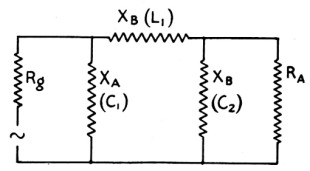
FIG. 3-EQUIVALENT CIRCUIT OF THE IMPEDANCE-MATCHING NETWORK
Such harmonic reduction as is obtained is due entirely to the effect of the plate tank condenser, and if a sufficiently high-C is used to obtain satisfactory harmonic reduction, the efficiency of the output circuit will be very materially reduced.
The tendency in the design of modern crystal-controlled transmitters is toward the use of very low values of tuning capacities in the tank circuit in order to obtain the best possible efficiency.
At the same time, the problem of harmonic suppression is becoming more serious every day.
The amateur bands are not harmonically related and stations operating on the high frequency part of the 80- and 40-meter bands have harmonics falling in channels assigned to other services.
Complaints are being made daily against amateurs who are permitting their harmonics to interfere with channels outside of the amateur bands, and it is imperative that drastic and effective measures be made to correct this situation.
The use of high-C circuits in the output stage of amateur transmitters would bring some relief, but it certainly is not desirable to impair the efficiency of the transmitter by this procedure.
The low-pass impedance-matching network, described herein, is the logical step towards complete elimination of harmonic difficulties without reducing the output on the fundamental.
A graphic illustration of the effectiveness of the impedance matching network in eliminating harmonics in one particular instance was obtained by listening to the second harmonic in a nearby receiver using, first, the conventional output system in the transmitter.
The harmonic was of such high intensity as to block the receiver.
After connecting and adjusting the filter, the second harmonic pick-up in the receiver was reduced to about the same amplitude as the harmonic being generated by the 47 crystal oscillator alone, and it could not be heard at all on a very sensitive receiver at a distance of about a mile.
And this effect was accompanied by an actual increase in the power delivered to the antenna.
|
|
| QST - February, 1934 | 17 |
|
NETWORK EFFICIENCY
Small diameter inductances have come very much in vogue in high frequency transmitters within the last year or so.
Their use is well justified in multi-stage transmitters because they have very small external fields and eddy current losses in shielding, etc., are reduced to a minimum.
A well-designed small coil will usually have a much higher Q than a large coil of heavy copper tubing.
But it is very difficult to couple inductively to one of these small inductances because of their small field and because of mechanical difficulties and losses in the pick-up coil form.
Repeated measurements have shown that the power in the antenna is usually increased from 20% to 30% when an impedance-matching network is substituted for a pick-up coil.
This increase is accounted for by the inherent high-efficiency of the network and by the elimination of the losses which might have been introduced by the pick-up coil.
Another reason for the better output is the fact that the antenna impedance can be precisely matched to the plate of the final amplifier tube, obtaining exactly the right relationship for optimum output with true resonance so that the voltage neither leads nor lags the current.
Substitution of the network system of coupling will usually result in a considerable increase of antenna current in an amateur installation with the same power input to the final amplifier.
NETWORK DESIGN
Usually neither the antenna input impedance nor the desired plate load impedance is accurately known in amateur installations, and so it is impractical to attempt quantitative design of a coupling network.
The experimental method of adjustment outlined above for obtaining the proper relationships is entirely satisfactory when the shunt and series arms are adjustable over wide ranges.
When the input and output impedances have been measured or can be calculated, it may be desirable to calculate the values of the filter elements.
|
Of course, conventional network theorems are employed, but two or three relations will be listed here for ready reference.1
Referring to Fig. 3, when the input and output impedances are pure resistances, the filter elements must satisfy the resonance equation:

Impedance match is expressed thus:
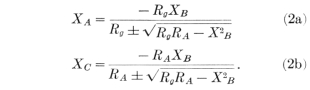
XB has a maximum value beyond which there is insufficient coupling for impedance match.
For sufficient coupling

The degree of harmonic attenuation can be determined from the known values of L1C1C2 by determining their reactance at the harmonic frequency and solving for power loss using conventional network theorems.
The author claims no particular novelty for this method of antenna coupling, since low-pass networks have been associated with vacuum tube output circuits for many years.
The particular system outlined above, however, has advantages over arrangements in which the plate is connected directly to the filter input, in that the system can be applied to existing transmitters with conventional tank circuits, and, also, because it is permissible to have the antenna reactance appear as a series arm in the output circuit, which is not desirable when a single pi section is used between the tube and the antenna.
The arrangement described above is so simple in construction and adjustment that it deserves wide spread application, especially in the high frequency field.
1Everett, “Output Networks for Power Amplifiers,” Proc. I.R.E. May 1931. —Editors.
|
|
| 86 & 88 | QST - February, 1934 |
|