|
|
|
| APOLLO SYSTEM TEST | |
|
Atop a Saturn rocket on the launch pad, the three Apollo astronauts will run through a detailed system checkout before the dramatic instant of liftoff. This will be the final test before the moment of truth. But this final test will have been preceded by hundreds of hours of testing, during which the equipment was subjected to some of the most stringent demands ever. One such group of equipment is the Apollo communication and data subsystem, provided by Collins and a team of subcontractors to North American Aviation, Inc., which installs the equipment in the command module it builds for the National Aeronautics and Space Administration. And the most extensive test in the C & D programs at Collins is the system test. It involves a complete operational test of system units individually, then testing each one with all other units that function together. All modes of operation are checked. Collins began systems tests of Block II Apollo equipment last January, and will continue until late this year. (Block II is the revised configuration Apollo equipment, intended for later Apollo flights and lunar landing. The lighter, more compact Block II equipment has sealed units containing more redundant features and providing greater flexibility than Block I equipment.) The C & D system will operate for both near-earth and deep-space communication. It will transmit and receive voice, telemetry, tracking, ranging, data and TV signals between. spacecraft and earth. It will also provide intercommunication for the astronauts, and communication between command module and lunar module or extra vehicular astronaut. |
|
|
The purpose of the system test is to prove the equipment complies with established circuit and system parameters and to determine affects on performance by varying parameters and operating conditions. Six main steps are involved in the system test: 1. Circuit reference tests of individual modes of operation. 2. A repeat of circuit reference tests with all modes operating. 3. Operating tests with varied thermal conditions. 4. Voltage standing wave ratio tests on all transmitting circuits, including antenna mismatches. 5. Parameter variation tests. 6. Electromagnetic interference tests. A circuit reference test is performed with only the equipment required to establish a particular circuit. In the case of a circuit reference test of S-band down-voice equipment, the audio center, pre-modulation processor, unified S-band equipment, and S-band power amplifier are energized. Detailed data for input and output levels, frequency response, carrier deviation, signal-to-noise ratio and other data are collected during this test. Following this are spot checks involving the units in the circuit reference test, but with the addition of pulse code modulation equipment, data storage equipment, up-data link, signal conditioners, central timing equipment and VHF/AM equipment. The performance of the equipment under these conditions is compared with data taken during circuit reference tests to determine if any degradation occurs due to operation of additional equipment. Parameter variation tests determine the affect of the variation in output/input level and frequency response of individual equipments upon over-all circuit performance. During these tests, variable gain and variable frequency response amplifiers are inserted between individual equipments in the circuit under test, and data is collected for a range of output/input levels and frequency characteristics. |
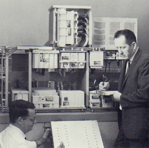 Collins engineers perform system test. Sherrill L. Zimmerman (left) - R.D. Carter (right) |
|
AU combinations of voice communication involving the three astronauts and all equipment for both flight and recovery modes are tested. Included are input/output signals involving the lunar module, which has a separate system. Collins conducts the system tests in its C & D system laboratory. Equipment made by Collins and its subcontractors is tested here individually, then the units are tested together in an equipment rack inside a standard screen room. The rack duplicates exactly the size, configuration, wiring and temperature of a section of the Apollo command module. Elaborate, time-consuming efforts go into the preparation of each phase of the system test, and the test equipment is precisely calibrated. In the Block II C & D system, Collins designed and is manufacturing the audio center, HF transceiver, pre-modulation processor, VHF recovery beacon and S-band power amplifier. Unified S-band equipment is provided by Motorola, VHF/AM transceiver by RCA, PCM telemetry equipment by Radiation, Inc., data storage equipment by Leach, and VHF triplexer by Rantec. Tested with the C & D system are central timing equipment, up-data link receiver, signal conditioner, C-band transponder, antennas and television system. Tests have been conducted by Collins on many communication systems in the quest for the highest possible quality and reliability standards. No tests, however, have been as detailed as those for America's manned lunar landing program. |
|
| —Collins Signal, Issue 61, Volume 14-3, 1966, Page 27 | |