|
|
|
| MERCURY'S COMMUNICATIONS - Launch, Orbit, Recovery | |
|
First details are released on the 14 electronic systems that will provide voice contact, radio command, beacon tracking and telemetry for the first manned satellite. FIRST PROTOTYPE of the complete communication system for Project Mercury, the National Aeronautics and Space Administration's manned satellite program, is scheduled for delivery early this summer to McDonnell Aircraft Corporation by Collins Radio Company. Collins' participation in Project Mercury consists of providing 14 electronic systems for these functions: Voice communication for the pilot during the orbital phase of the mission; command functions within the capsule during launch, orbit and re-entry phases of the mission; telemetry of scientific and aero-medical data during the launch, orbit arid re-entry phases; tracking of the satellite during the orbital phase of the mission; rescue functions of voice communication and rescue beacons to be used when the satellite is brought back to earth, and antennas for all phases of the mission. The Collins voice communication equipment to be furnished will operate in both the HF and UHF ranges. The HF voice function will consist of an HF Orbital Voice Communication Transmitter-Receiver and an HF Recovery Voice Communication Transmitter-Receiver. The transmitter for the HF Orbital Voice function is a conventional crystal-controlled, partially transistorized unit with 10 watts of output power, and the completely transistorized receiver is a high-performance, tuned radio frequency circuit with a crystal input filter. The HF Orbital Voice unit operates directly from a central 28 volt battery supply. |
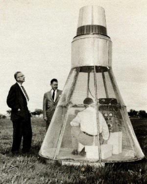 Arthur A. Collins (left), President, and Dr. Harold V. Gaskill, VP, Planning, examine full-scale antenna test mockup. |
|
The HF Recovery Voice Transmitter-Receiver will be identical to the HF Orbital Communication set except that an additional 24 hour battery pack will be used as the power source. The power amplifier is omitted, which reduces the power output lo 1 watt for battery economy. The UHF Orbital Voice Transmitter is crystal-controlled with a power output of two watts. The receiver is a completely transistorized, high performance, single-conversion superheterodyne. Both the transmitter and receiver will operate from a central 28 volt power source. The UHF Back-Up Voice Transmitter-Receiver will be identical to the UHF Orbital Communication set except that the power output will be one-half watt. All the HF and UHF equipment will consist of single, foam-encapsulated units to achieve light weight and rugged construction with minimum volume. | |
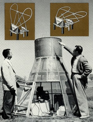 DESCENT-RECOVERY UHF antenna (top of capsule at left), is used after antenna fairing is blown off in descent. The UHF antenna is in collapsed position (inset right under fairing, erecting automatically (inset left) when fairing is blown off. |
Controls Centralized Communication subsystem manual controls will be provided by a common control unit, which will contain audio volume controls, a UHF Rescue Transceiver Voice-DF switch, a key for CW transmission and audio-mixing provisions. The manual control unit will be built by Collins, while the audio electronic control center will be supplied by Andrea Radio, Inc., Long Island City, N. Y., under subcontract to Collins Radio Company. The command subsystem, which will consist of two FM command receivers with paralleled inputs and outputs to provide redundant operation, will allow the operation of 20 “on-off” (DPDT) functions of which any 6 may be operated simultaneously. The audio output of the receivers will also be paralleled and used for emergency voice communication. Motorola, Inc., Phoenix, Ariz., under subcontract to Collins, will supply this unit, which is completely transistorized and mechanically designed to permit satisfactory performance in the expected environment. Power source for the unit will be the 28 volt central power supply. Texas Instruments, Inc., Dallas, Tex., will provide Project Mercury's telemetry subsystem under subcontract to Collins Radio Company. The telemetry subsystem consists of a high-power telemetry transmitter, a low-power telemetry transmitter and a telemeter-transmitter power supply. The PMT-A4 high-power telemetry transmitter will be used for intermittent services and will transmit scientific and aero-medical information. A modified version of the Texas Instruments PMT-A4 will be used for the low-power telemetry transmitter for continuous telemetry of aero-medical information. Since both of the Texas Instruments telemetering transmitters have a vacuum tube output stage, a transistorized high voltage power supply will be utilized. A separate circuit will be used for each transmitter, but both will be housed in the same physical unit. The precision tracking subsystem, which will be furnished by the Avion Division of the American Car and Foundry Co., Paramus, New Jersey, under subcontract to Collins, consists of a C-band tracking beacon, a C-band power supply, an S-band tracking beacon and an S-band power supply. The C-band beacon unit has a receiver sensitivity of -65 dbm and a peak power output of 375 watts, which makes it capable of 1000 mile range. This unit is transistorized except for a magnetron in the transmitter. The S-band beacon unit also has a receiver sensitivity of -65 dbm and a 1000 mile capability range. The S-band unit is transistorized except for a pencil triode in the transmitter. |
|
Coverage With Simplicity Simmonds Aerocessories, Inc., Tarrytown, New York, under subcontract to Collins Radio, will provide the equipment for the two rescue beacon functions provided for recovery, which will include an HF rescue beacon and UHF rescue beacon. A modified version of Simmonds SEA-SA VE beacon, which will deliver 1 watt of output, will be utilized for the HF rescue function. A modified Simmonds SARAH beacon, which will deliver 15 watts of peak pulse, will be used for the UHF rescue beacon function. |
|
|
Two criteria were used in choosing antennas for all Project Mercury's communications - radiation pattern coverage and simplicity (reliability). Reception of signals on the ground or at the vehicle is predicated on having a roll stabilized vehicle. In order to conserve energy, the majority of the radiated energy is directed toward the earth in a rough approximation of hemispheric coverage. One antenna will be utilized for all functions, except the C- and S-band beacons, during launch and orbit. When the drogue chute is ejected, the common antenna will be jettisoned, and a broadband monopole will be erected from the top of the parachute container. At this time the UHF voice, command, and telemetry functions will be multiplexed to this antenna, which is named the UHF Descent Recovery Antenna. After the vehicle lands and the parachute is separated, a balloon having aerodynamic lift will be released. This balloon will support the HF wire antenna which radiates HF beacon and HF communication signals. The UHF Descent Recovery Antenna will operate constantly, and in case of a balloon failure, all radios will not become inoperative at once. C- and S-Bands During launch and orbit, the common antenna that serves all transmitters and receivers, other than the C- and S-band units, is a modified biconical horn that separates the nose cone from the vehicle proper. Collins is furnishing the UHF Descent Recovery Antenna, the HF wire antenna, the HF diplexer, and the bicone tuning mechanism. The bicone multiplexer will be furnished under subcontract to Collins by Microphase, Inc., Greenwich, Conn. General Mills, Inc., Minneapolis, Minn., under subcontract, to Collins will furnish the balloon system. Melpar, Inc., Falls Church, Va., under subcontract, will provide the C- and S-band antenna. |
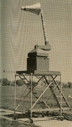 ONE-THIRD scale model of the Project Mercury capsule is mounted on pattern range rotator (top) at the Collins antenna testing range for radiation characteristics measurements. |
| —Collins Signal, Issue 36, Volume 7-4, 1959 - Pages 25-27 | |